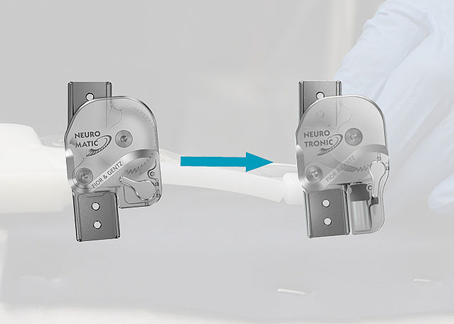
Special Work Steps when Producing a KAFO with a NEURO MATIC
In this online tutorial, you can find information on special work steps that you need to consider when producing an orthosis with the automatic system knee joint NEURO MATIC. This includes the placement of dummies, the particularities of the reinforcement process and the handling of the cable cover conduit.
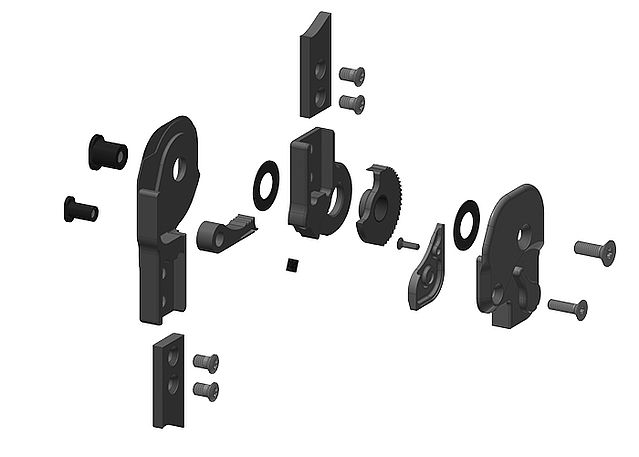
Here you can find step-by-step instructions for the assembly of a NEURO MATIC system knee joint.
-
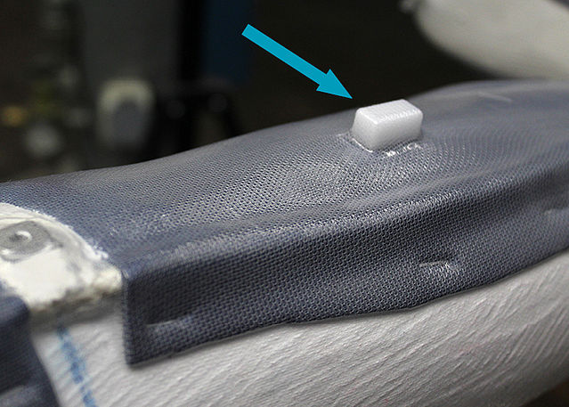
Preparing the Reinforcement
-
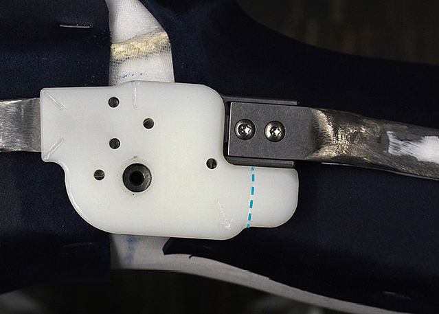
Step 1/7
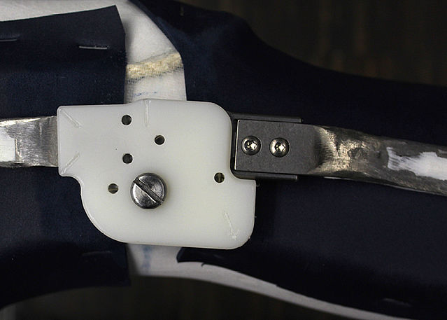
Step 2/7
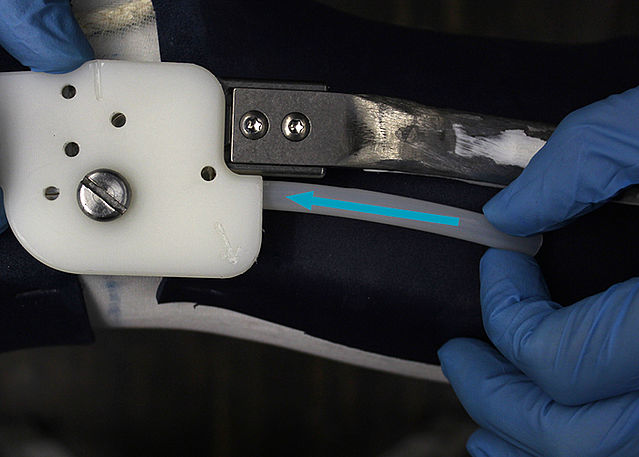
Step 3/7

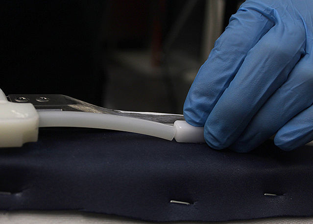
Step 4/7
Step 5/7
Step 6/7
Step 7/7


-
Reinforcing the KAFO
-
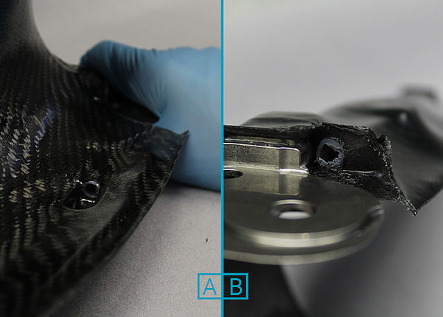
Step 1/3
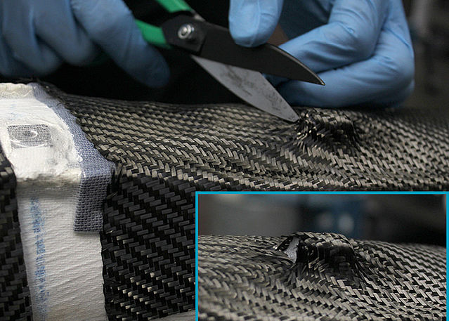
Step 2/3
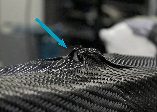
Step 3/3


-
Laminating the KAFO
-
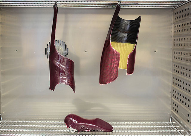
Step 1/2
Step 2/2


-
Cutting the KAFO
-
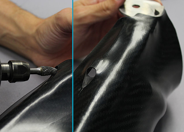
Step 1/3
Step 2/3
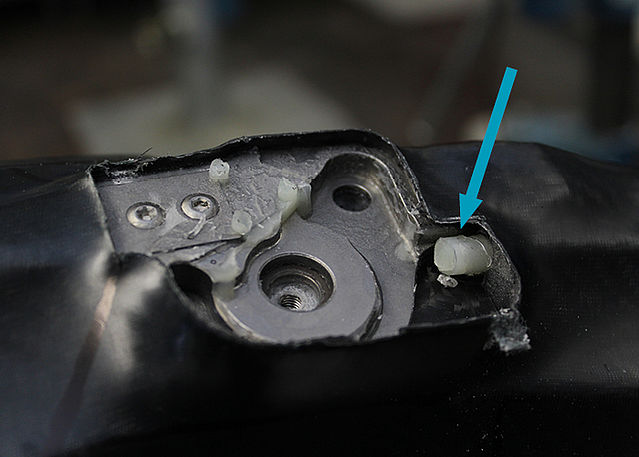
Step 3/3


-
Tempering and Grinding the KAFO
-
Step 1/2
Step 2/2


-
Mounting System Joints
-
Step 1/1
Last Update: 24 April 2024