Special Work Steps when Producing a KAFO with a NEURO TRONIC
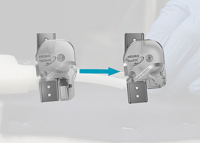
This online tutorial provides you with information on special work steps that need to be followed when producing an orthosis with the automatic system knee joint NEURO TRONIC. This includes the placement of dummies and the specifics of reinforcement. For general reinforcement instructions, see the online tutorial KAFO in Joint Lamination Technique.
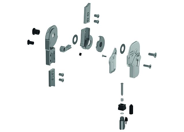
Here, you can find step-by-step instructions for the assembly of a NEURO TRONIC system knee joint.
-
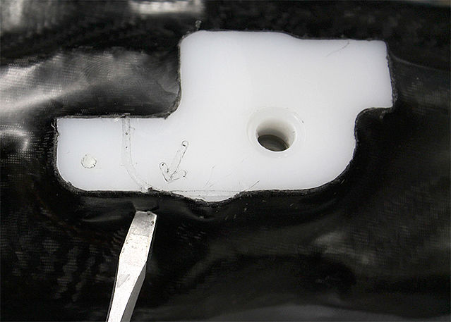
Preparing the Reinforcement
-
Step 1/10
Step 2/10
Step 3/10
Step 4/10
Step 5/10
Step 6/10
Step 7/10
Step 8/10
Step 9/10
Step 10/10


-
Reinforcing the KAFO
-
Step 1/3
Step 2/3
Step 3/3


-
Laminating the KAFO
-
Step 1/2
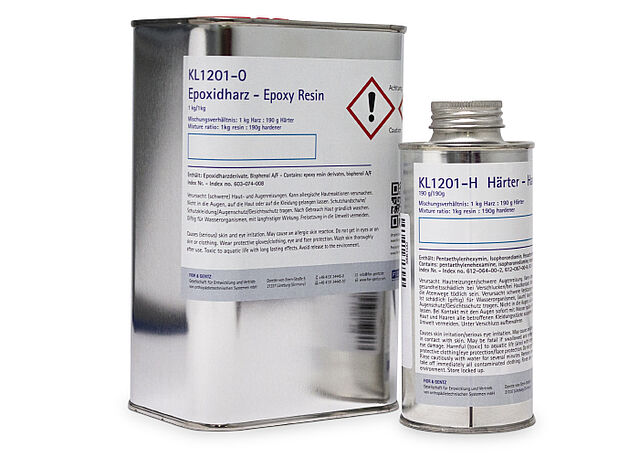
Step 2/2


-
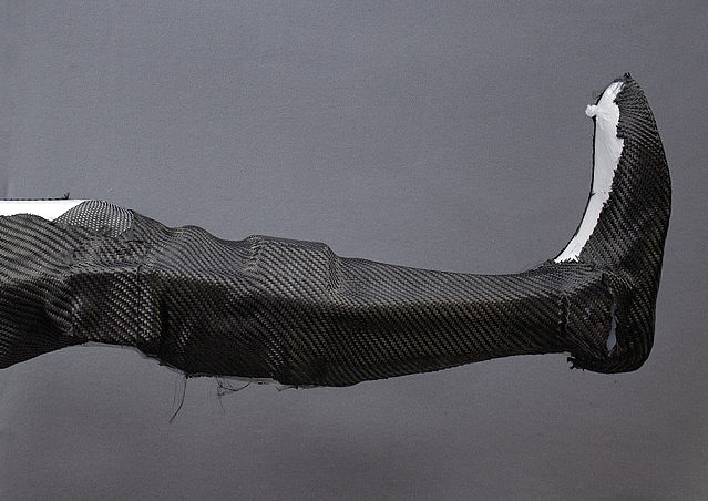
Cutting the KAFO
-
Step 1/2
Step 2/2


-
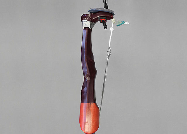
Tempering and Grinding the KAFO
-
Step 1/3
Step 2/3
Step 3/3


-
Mounting the System Joints
-
Step 1/1
Last Update: 23 April 2024