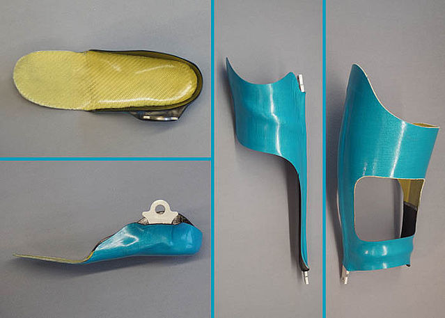
KAFO with Carbon System Joints in Anchor Lamination Technique
Using NEURO SWING Carbon and NEURO LOCK Carbon as an Example
This online tutorial shows the production of a KAFO with our water-resistant system joints, using as an example the:
- NEURO SWING Carbon system ankle joint
- NEURO LOCK Carbon system knee joint
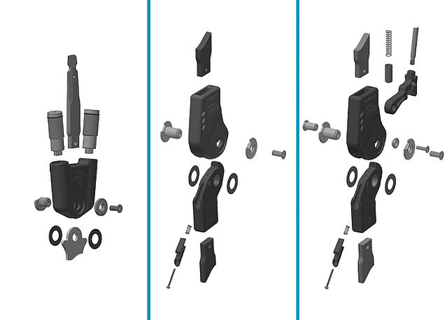
The NEURO SWING Carbon as well as the NEURO LOCK Carbon are water-resistant system joints that are especially light thanks to their carbon fibre reinforced joint case and are equipped with a seawater-resistant stainless steel screwing. Due to their specific sleeves, the spring units of the NEURO SWING Carbon are as water-resistant as the carbon fibre reinforced locking parts of the NEURO LOCK Carbon.
Due to the properties of the carbon system joints, the production technique for a KAFO (knee-ankle-foot orthosis) differs from the joint lamination technique or anchor lamination technique with system joints made of steel or titanium. The system anchors, for example, are specifically designed for these carbon system joints.
You can find the joint assembly of the carbon system ankle joints, using the NEURO SWING Carbon as an example, and the joint assembly of the carbon system knee joints, using the NEURO LOCK Carbon as an example, in the Producing the Orthosis section under the Options & Extras.
-
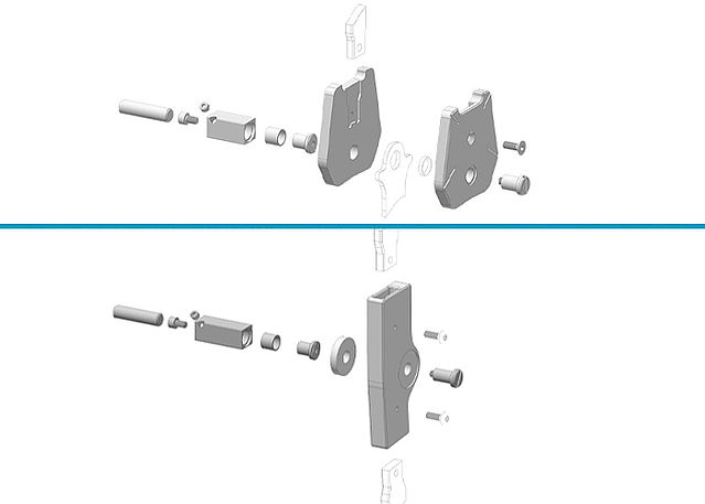
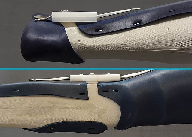
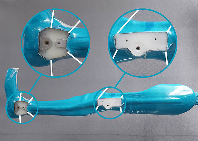
Mounting the Assembly/Lamination Dummys
-
Step 1/1
-
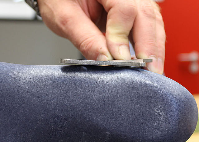
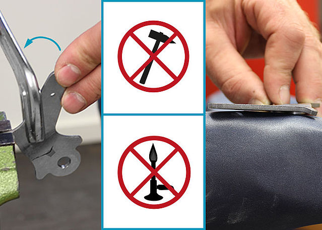
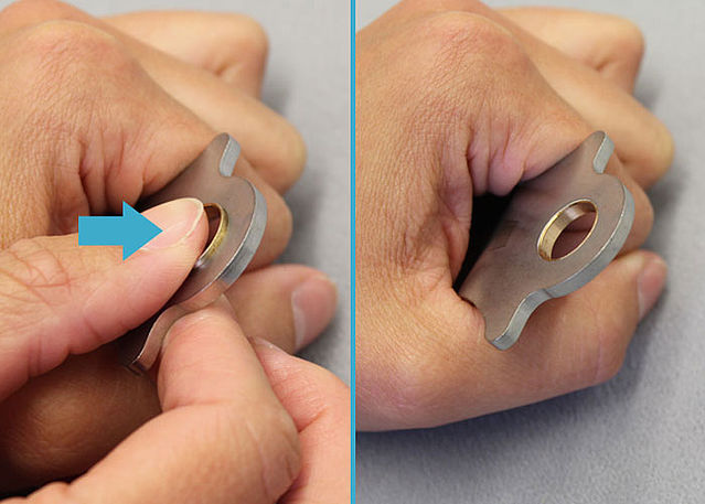
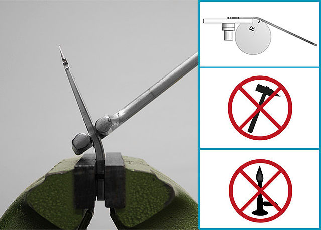
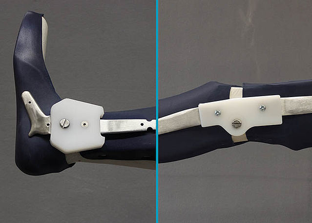
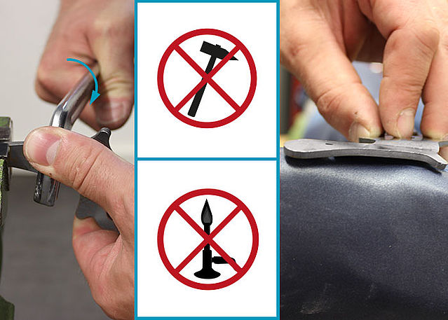
Bending the System Stirrups/Anchors
-
Step 1/10
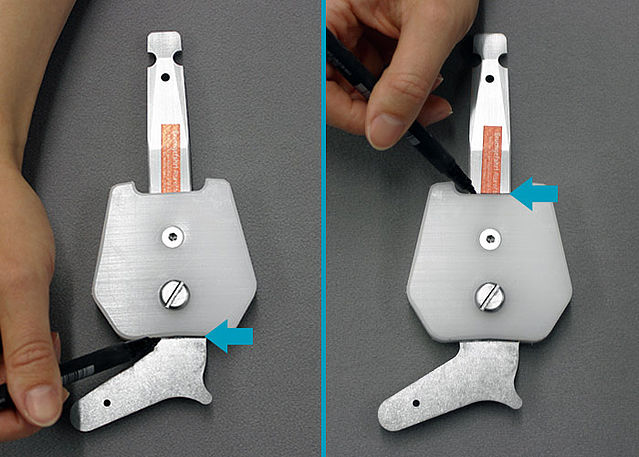
Step 2/10
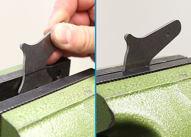
Step 3/10
Step 4/10
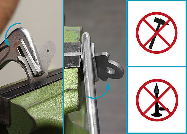
Step 5/10
Step 6/10
Step 7/10
Step 8/10
Step 9/10
Step 10/10


-
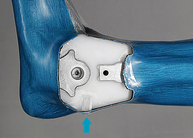
Reinforcing and Laminating the KAFO
-
Step 1/1
-
Cutting the KAFO
-
Step 1/4
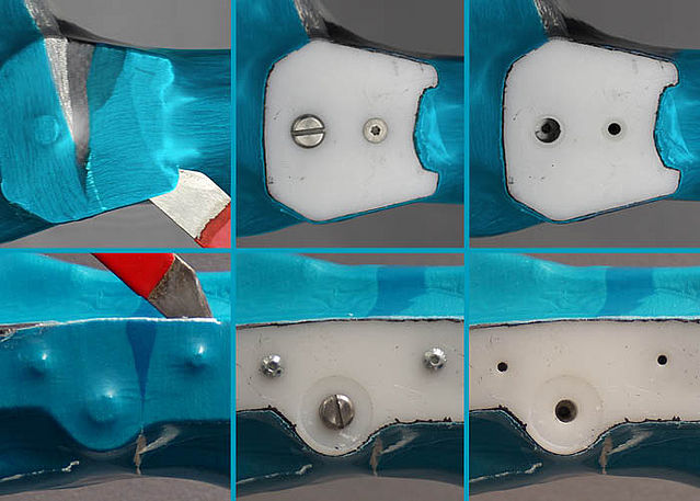
Step 2/4
Step 3/4
Step 4/4


-
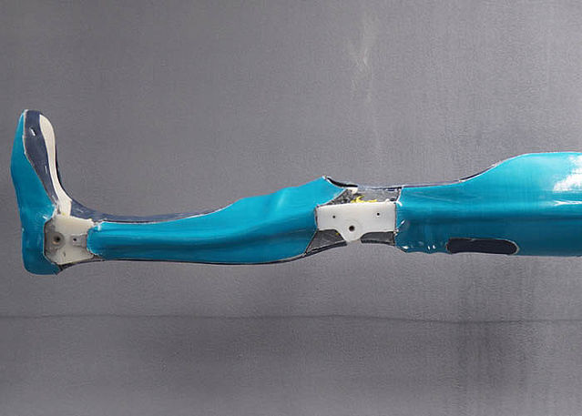
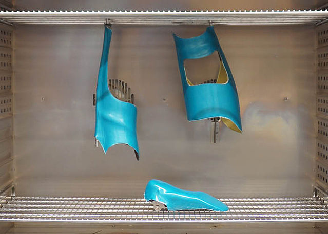
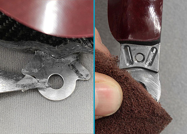
Tempering and Grinding the KAFO
-
Step 1/4
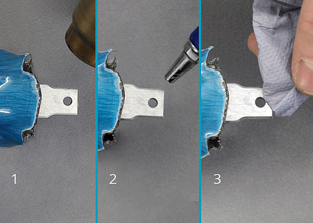
Step 2/4
Step 3/4
Step 4/4


-
Mounting the System Joints
-
Step 1/1
Last Update: 27 October 2020