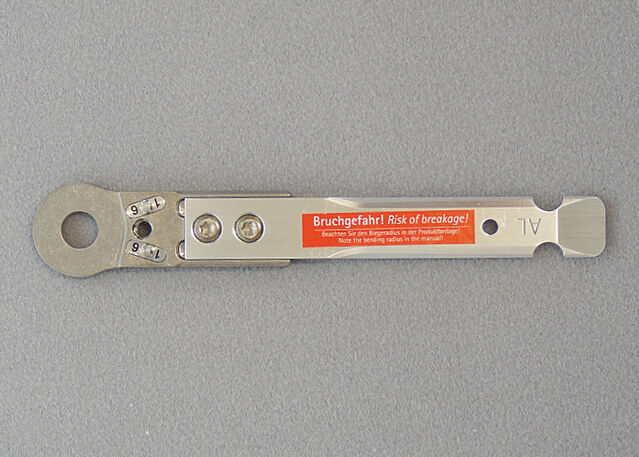
Bending System Stirrups/Anchors
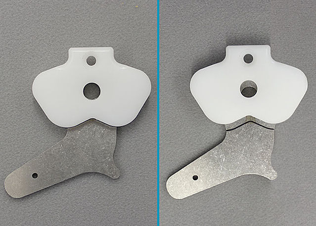
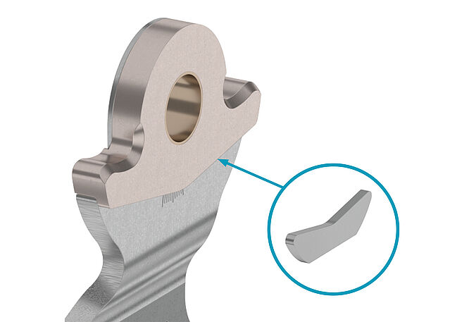
System anchors are connecting elements. In the Anchor Lamination/Prepreg Technique and the Joint Lamination/Prepreg Technique, they are embedded into the laminate. When producing a custom-made orthosis, it is necessary to adapt the system stirrups and anchors. Depending on the material, a defined bending radius should be observed during bending in order to ensure stability.
You can find the bending radii for system stirrups and anchors in different materials in the instructions for use.
-
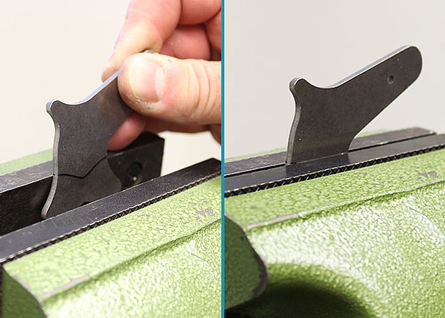
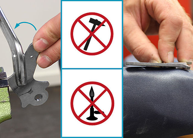
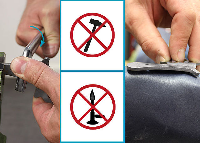
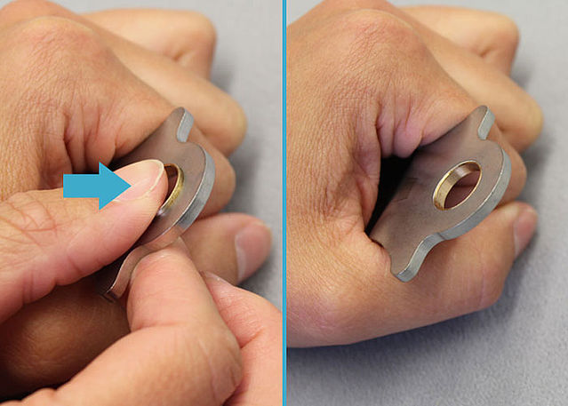
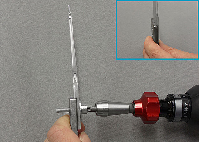
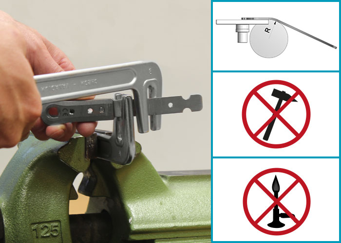
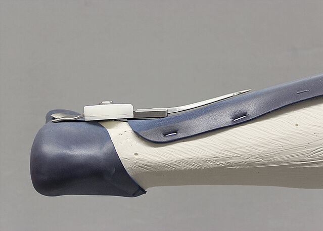
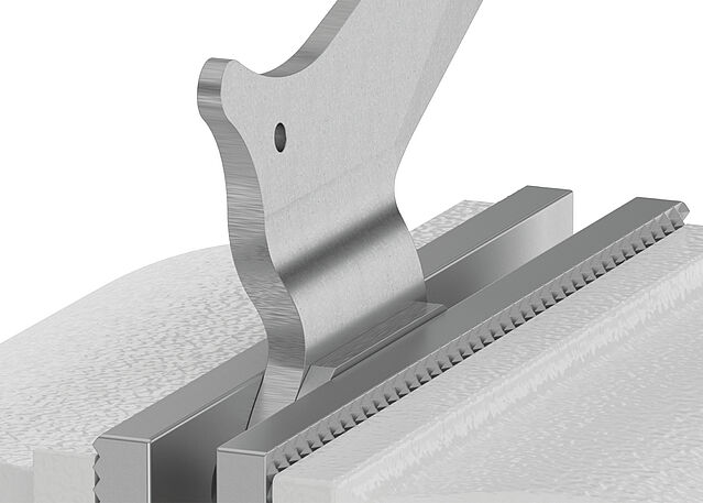
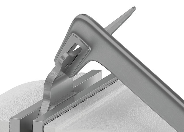
Bending the System Stirrups/Anchors
-
Step 1/12
Step 2/12
Step 3/12
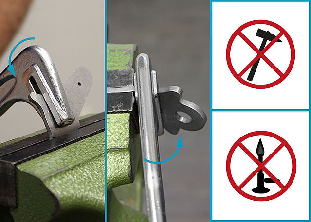
Step 4/12
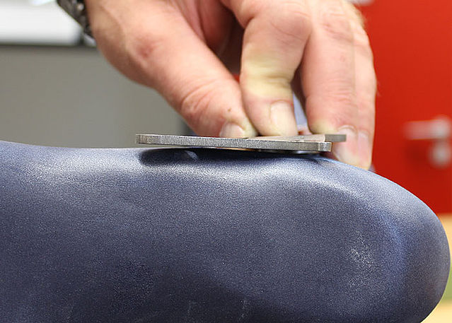
Step 5/12
Step 6/12
Step 7/12
Step 8/12
Step 9/12
Step 10/12
Step 11/12
Step 12/12


-
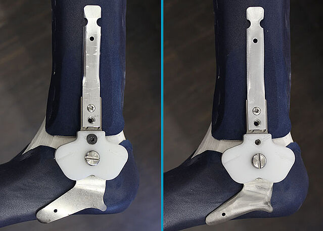
NEURO SWING 24mm
-
Step 1/3
Step 2/3
Step 3/3


Last Update: 27 March 2024