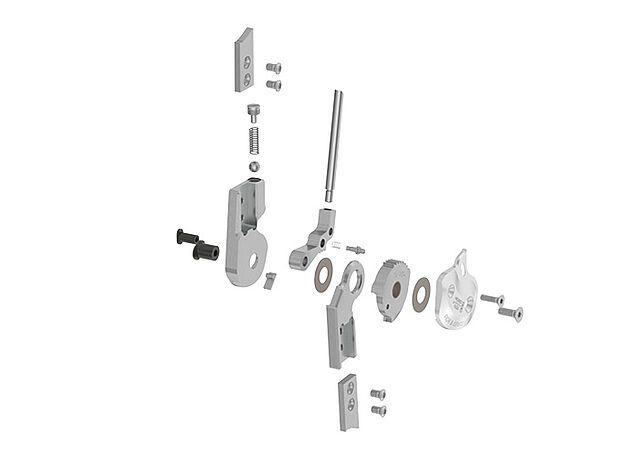
Joint Assembly
NEURO FLEX MAX Step Lock Function
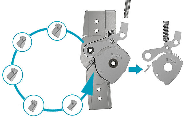
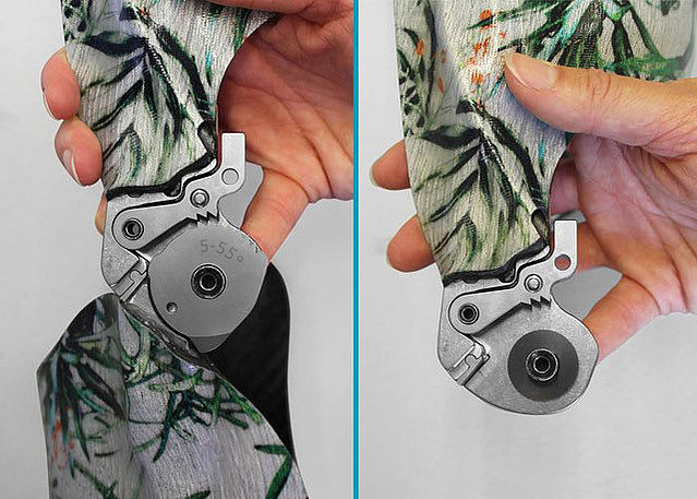
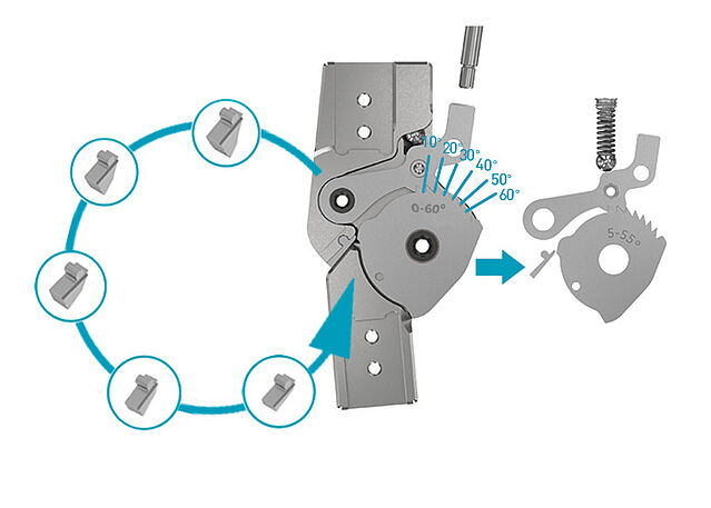
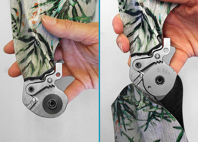
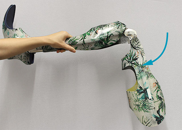
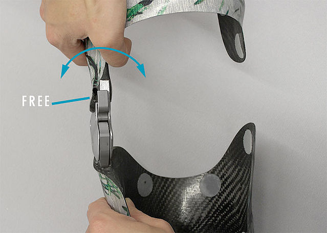
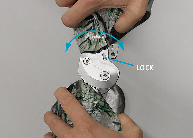
This online tutorial shows the joint assembly for the locked system knee joint NEURO FLEX MAX with step lock function. This function enables a gradual locking of the system joint from a flexed position of 55° or 60° in 10° steps to the required flexed position (which is premounted at 5°). When using the lock lever and the fixing pawl, the system joint can even be permanently unlocked. This way, the patient can perform physiotherapeutic exercises or ride a bike and drive a car unhindered – without having to take off the orthosis.
You will find all important information on step lock pawls, extension stops and conversion options in the instructions for use. The NEURO FLEX MAX is also available with a stepless lock function. The system knee joint, with lock function as well as with step lock function, provides an alternative function by exchanging the step lock stop disc and cover plate.
-
Joint Assembly NEURO FLEX MAX Step Lock Function
-
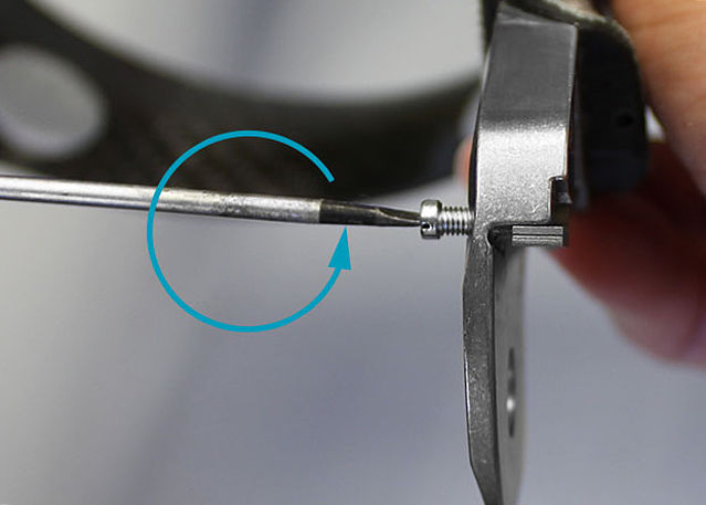
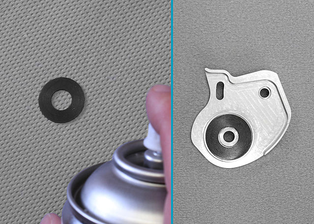
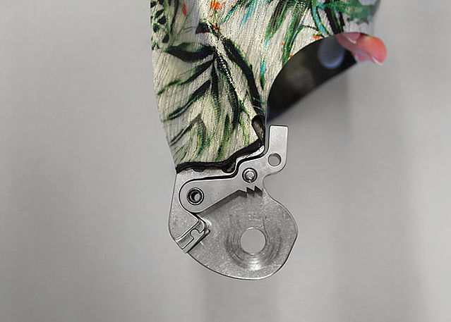
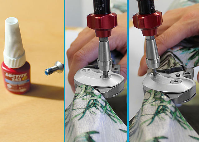
Step 1/26
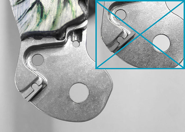
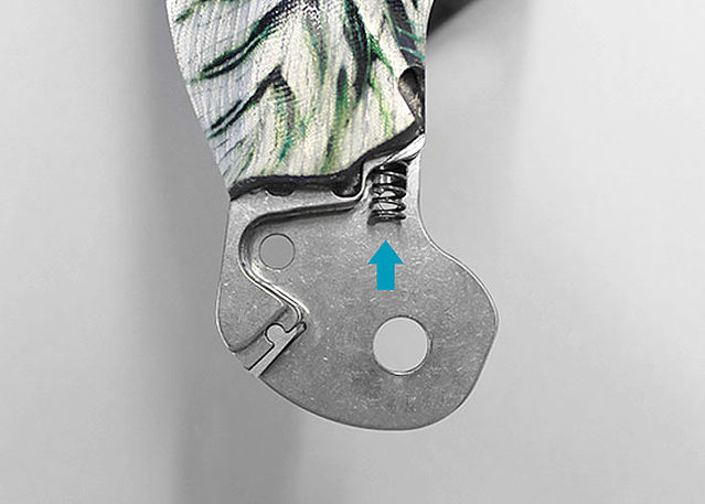
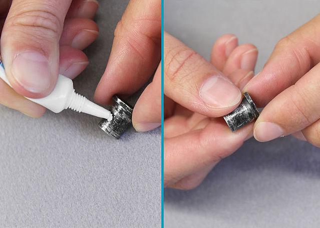
Step 2/26
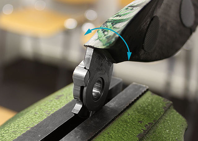
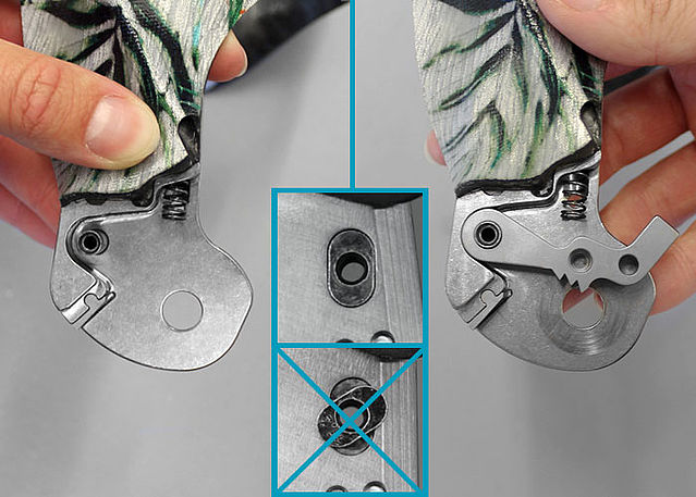
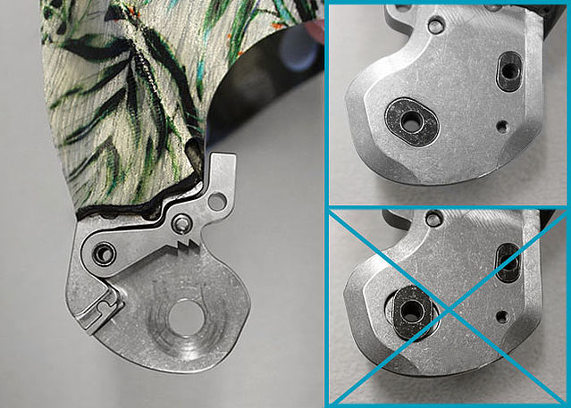
Step 3/26
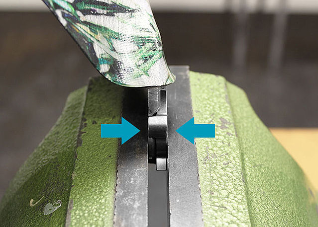
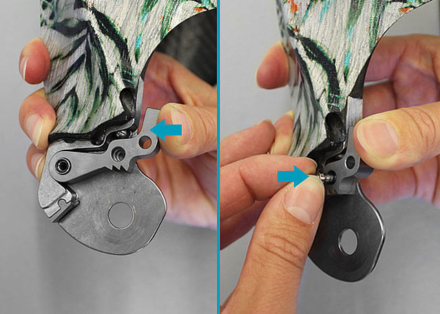
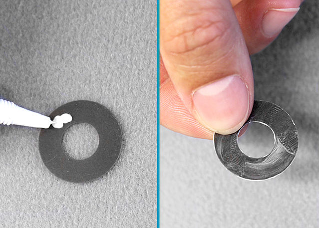
Step 4/26
Step 5/26
Step 6/26
Step 7/26
Step 8/26
Step 9/26
Step 10/26
Step 11/26

Step 12/26
Step 13/26
Step 14/26
Step 15/26
Step 16/26
Step 17/26
Step 18/26
Step 19/26
Step 20/26
Step 21/26
Step 22/26
Step 23/26
Step 24/26
Step 25/26
Step 26/26


Last Update: 15 February 2023
Last Update: 16 June 2020