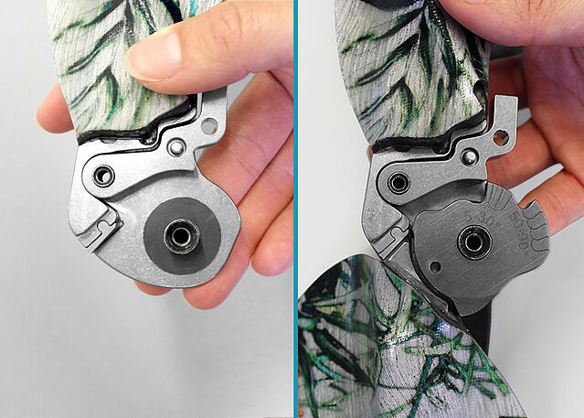
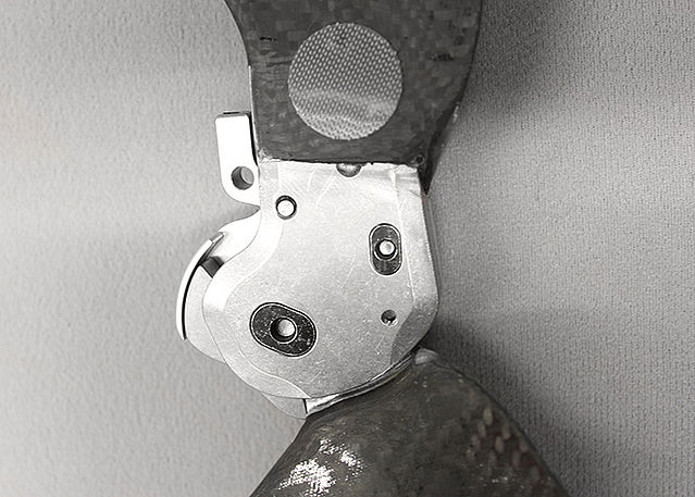
Joint Assembly
NEURO FLEX MAX Alternative Function
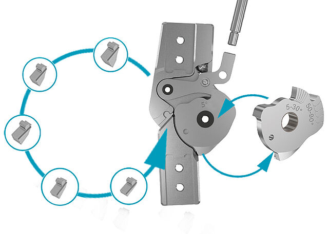
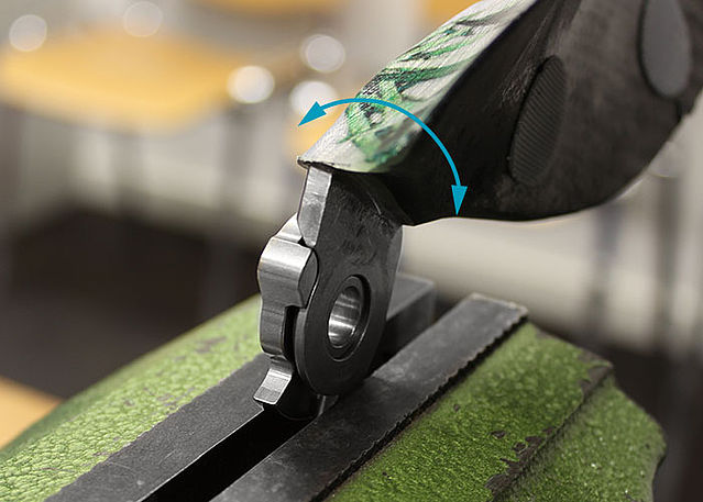
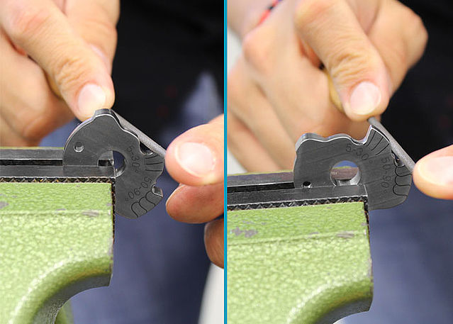
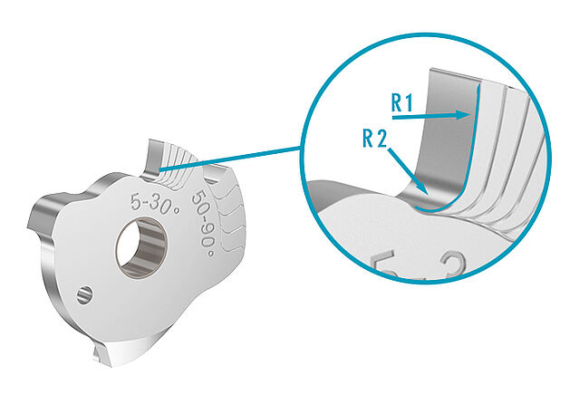
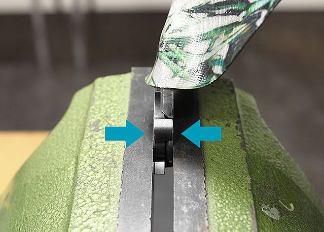
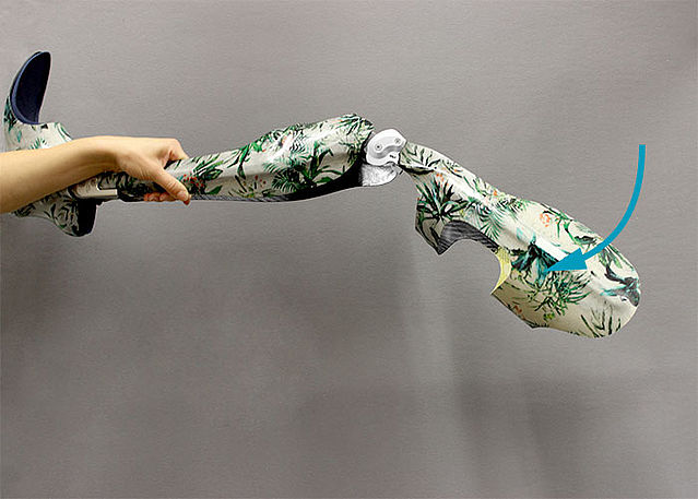
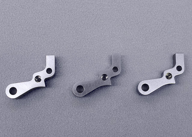
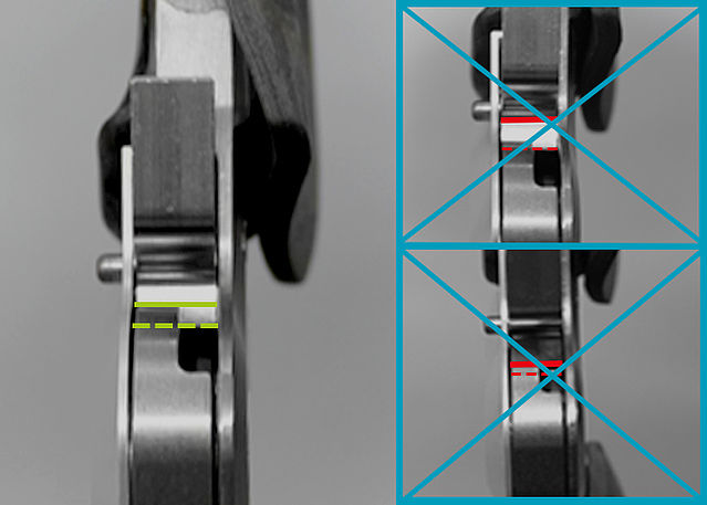
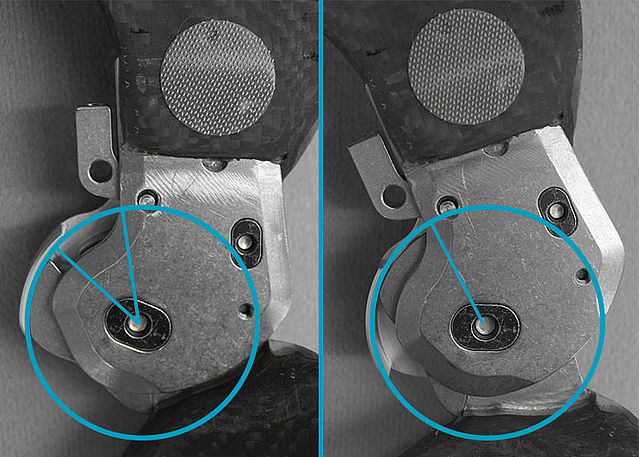
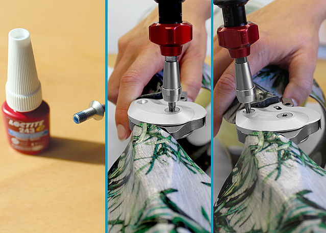
This online tutorial describes the alternative function of the locked system knee joint, which is an expansion of the system joint's main functions. By mounting the flexion stop disc AF and the cover plate AF and filing it accordingly, the unlocked NEURO FLEX MAX can be used as a locked system joint with adjustable limitation of the maximum knee flexion angle.
You will find all important information on locking pawls, extension stops and conversion options in the instructions for use. The NEURO FLEX MAX is available with lock function or step lock function.
-
Joint Assembly NEURO FLEX MAX Alternative Function
-
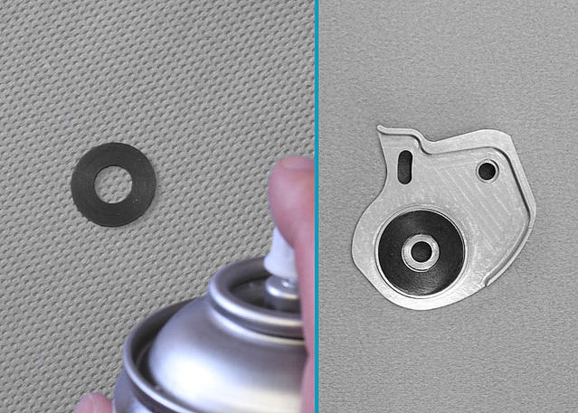
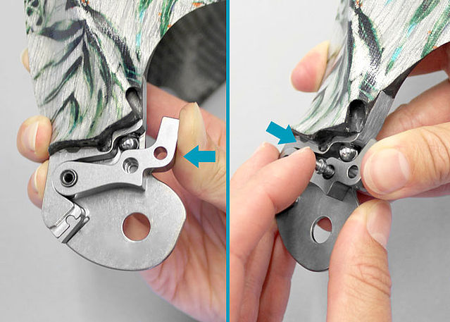
Step 1/29
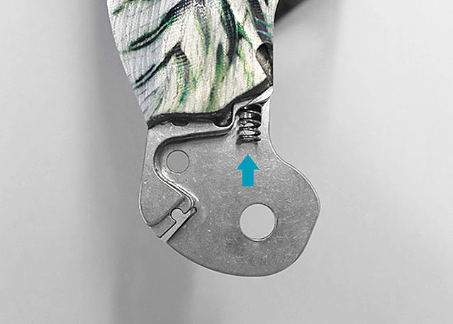
Step 2/29
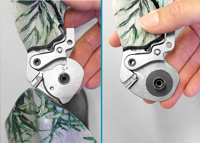
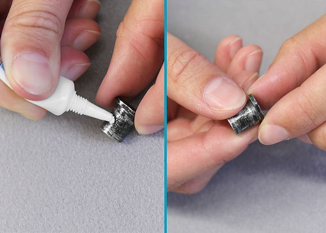
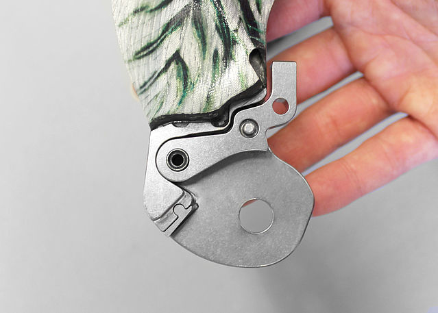
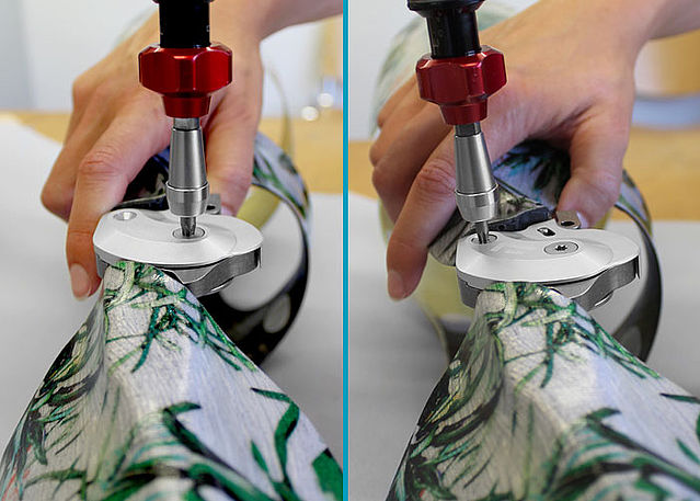
Step 3/29
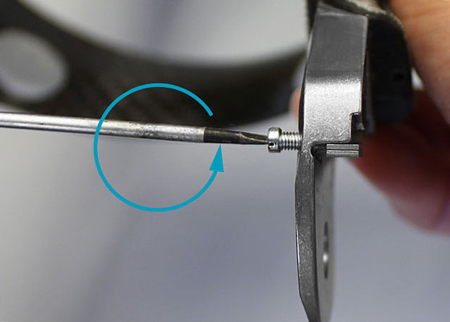
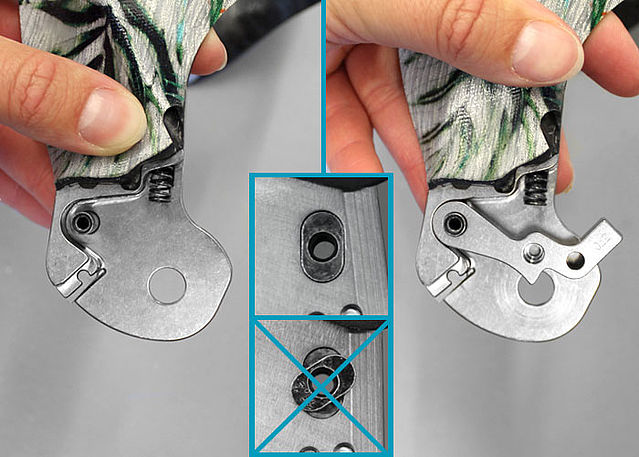
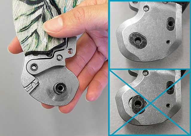
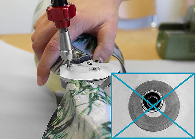
Step 4/29
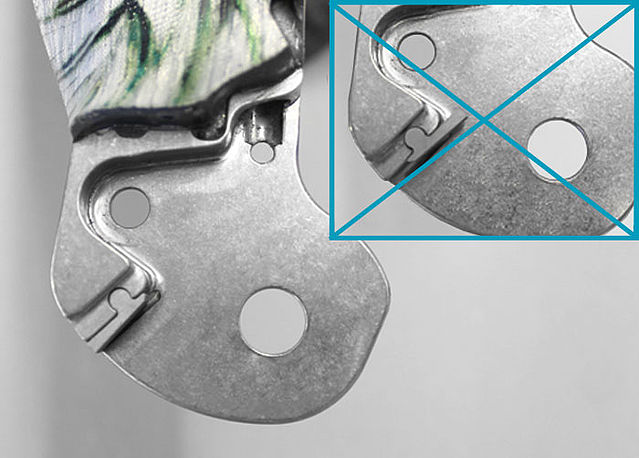
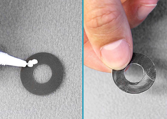
Step 5/29
Step 6/29
Step 7/29
Step 8/29
Step 9/29
Step 10/29
Step 11/29
Step 12/29
Step 13/29
Step 14/29
Step 15/29

Step 16/29
Step 17/29
Step 18/29
Step 19/29
Step 20/29
Step 21/29
Step 22/29
Step 23/29
Step 24/29
Step 25/29
Step 26/29
Step 27/29
Step 28/29
Step 29/29


Last Update: 15 February 2023
Last Update: 16 June 2020