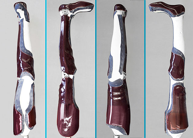
Flexible Seating Area
when producing a KAFO
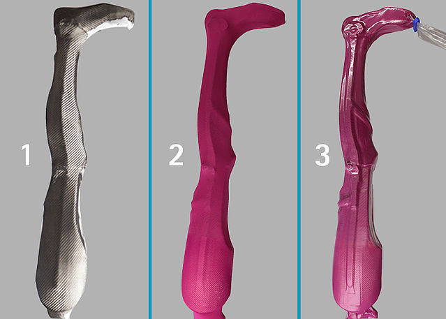
A laminated orthosis is made of different materials that are combined with each other. The objective is to achieve maximum stability at a very light weight. Furthermore, however, aesthetics and comfort play an important role for the user as well.
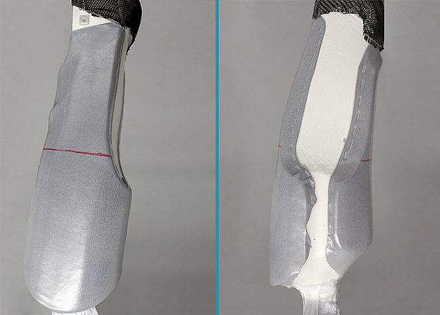
A KAFO (Knee-Ankle-Foot Orthosis) with a flexible seating area offers the necessary stability when walking and standing and adapts to the body when sitting. This tutorial provides a step-by-step description of all the things that need to be considered.
-
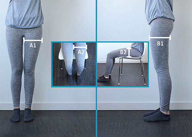
Thigh Measurements
-
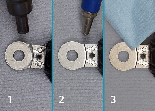
Step 1/1
-
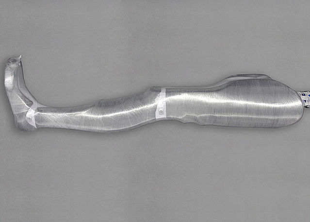
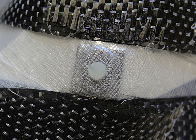
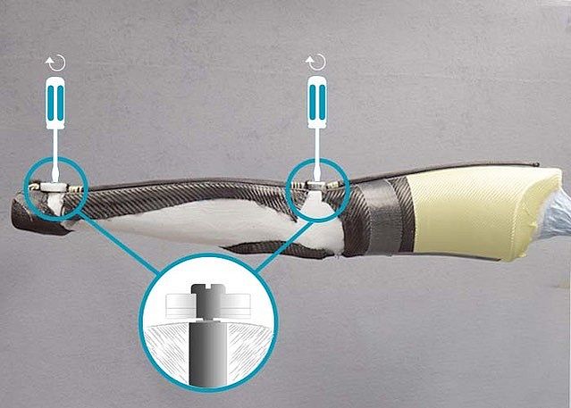
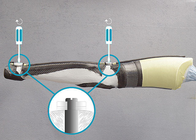
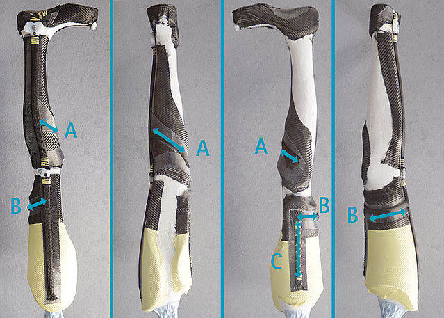
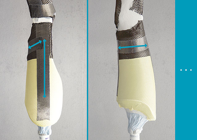
Reinforcing the Femoral Shell
-
Step 1/13
Step 2/13
Step 3/13
Step 4/13
Step 5/13
Step 6/13

Step 7/13
Step 8/13
Step 9/13
Step 10/13
Step 11/13
Step 12/13
Step 13/13


-
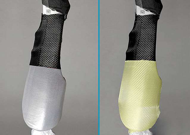
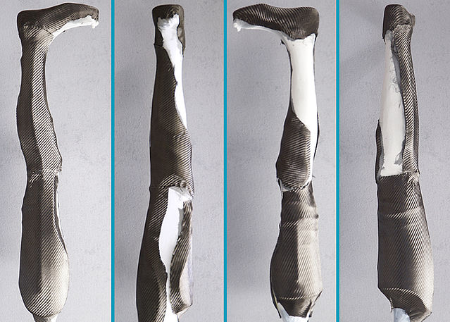
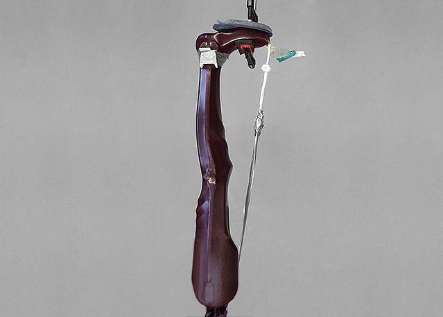
Laminating the Femoral Shell
-
Step 1/2
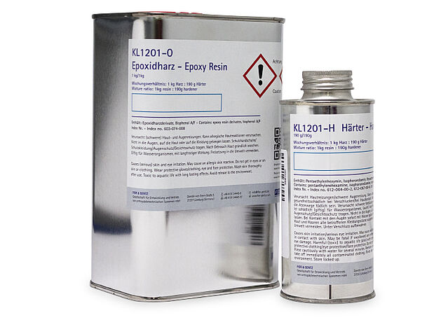
Step 2/2


-
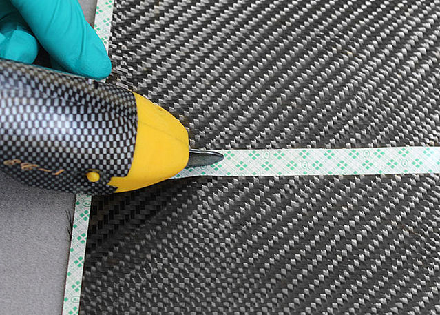
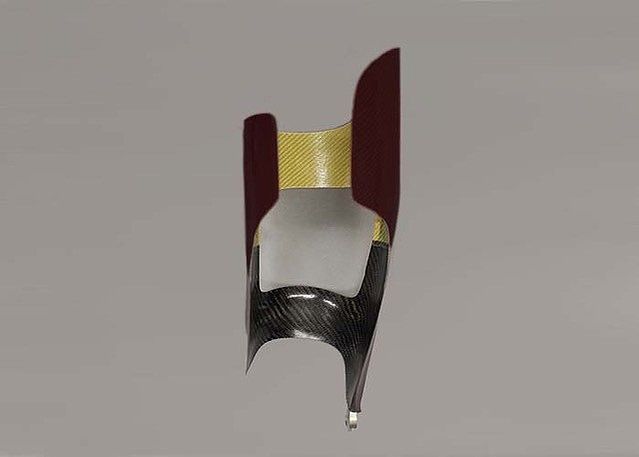
Cutting the Femoral Shell
-
Step 1/2
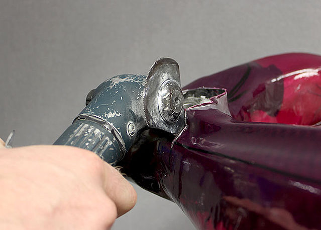
Step 2/2


-
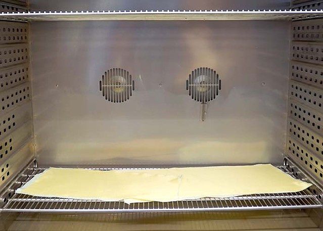
Tempering and Grinding the Femoral Shell
-
Step 1/3
Step 2/3
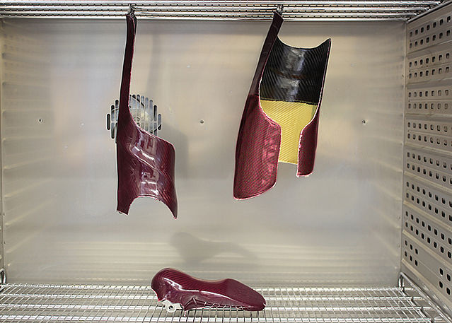
Step 3/3


Last Update: 07 May 2020